Robotics Controllers Multipoint Digital I/O & 24Ch A/D & D/A (Commercial and Military)
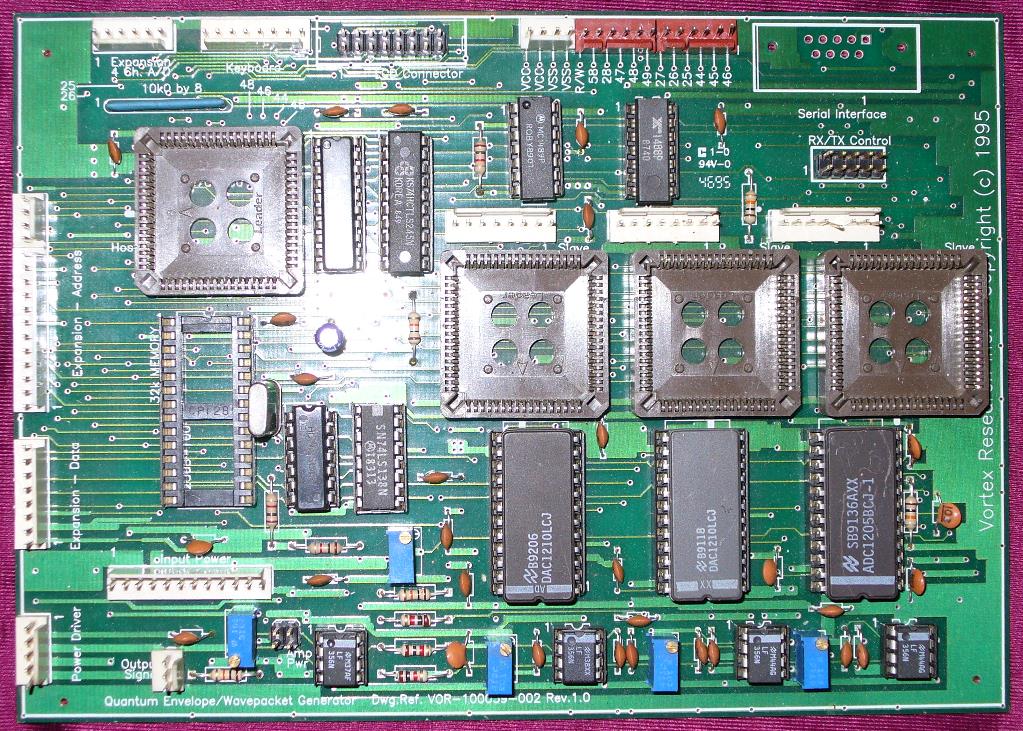
Complex Waveform Generators (Commercial and Military)
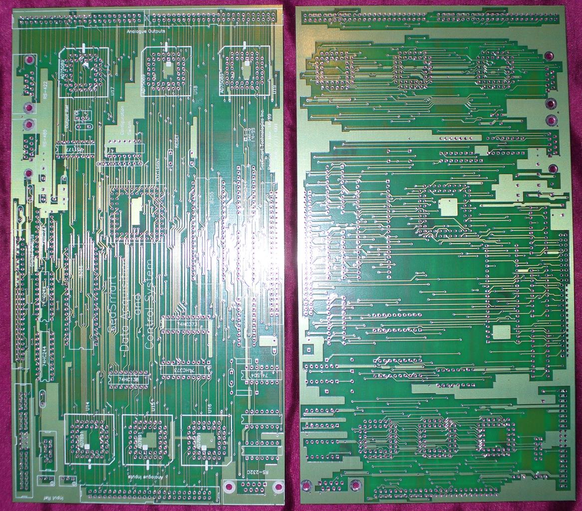
16/24 Channel Electric Fence Detection and System Controller
Fast Prototyping and Concept Proofing (Lake/Ocean bottom Silt Level Detection)
Cellulose Ethanol Processing and Co-Generation
Hydroponic Lighting and Robotics
Detection / Reconnaissance Different Methods of Detection in Security Systems (more information to be added, I just never know how much I’ll add)
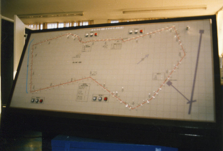
Before we get started here, let me just say that the “myth” that one cannot measure a lethal or non-lethal high voltage line and perform accurate alarm point detection “in-situ” is dead wrong, we were doing it in 1986 on fences 5km long on a side with multiple “hot” lines.
In-situ
Ratiometric Differential Current Analysis - High voltage and current is sent into a loop using a boost transformer and two CT’s or shunts. This is a system based on a differential ratio of currents collapsing towards a single point of a broken loop, at which point, current sinks to a ground based return path. Detection becomes a function of Ai:Bi as outlined below (with notes from the actual software);
* Few Notes on System Operation, * * The system has 4 pairs of hall effect transducers that monitor * the active current in both HT loops. Each pair of hall effect * transducers are tied to a pair of A/D's. The quiescent current or * average current in the system under normal conditions is set * nominally at a reading of 10. An open circuit on any pair will force * both converters to read <= 5. A short circuit between HT phases * causes an immediate result of 1023 in unattached loops. A short * between loop wires causes an alteration in the average current of the * transducers (an upward increase) that maintains equivalency. Any of * the above situations will cause a status fault of the type indicated. * The main function of the transducers is to perform paired * ratiometric analysis on the loop. Changes in environmental * conditions that cause resistance changes in the ground loop have no * effect on the analysis. The formula for analysis is as follows, * * [ (L*2) ] * X = [ ------- ] * Ia * [ (Ia+Ib) ] * * Where - L equals the length of the fence in metres or feet * - Ia equals the lower hall effect value (0 to 1023) * - Ib equals the higher hall effect value (0 to 1023) * * If L=2000 and the alarm is at 1500 metres then the values will be * as follows (using an 8 bit (256) standard), * * Ia = 3/8 of 256 or 96 and Ib = 5/8 of 256 or 160 * * The formula will then operate as follows, * * [ (2000*2) ] 4000 * X = [ ---------- ] * Ia = ------ * Ia = 15.626 * 96 = 1500 * [ (96+160) ] 256 * * If as metioned earlier the ground plane efficiency changes, there can * be an xx % alteration in both hall effect values. The alteration for * 20 % change could be shown as follows, * * [ (2000*2) ] 4000 * X = [ ---------- ] * Ia = ------ * Ia = 13.029 * 115 = 1498.37 * [ (115+192) ] 307 * * If L=2000 and the alarm is at 1500 metres then the values will be * as follows (using an 10 bit (1024) standard), * * Ia = 3/8 of 1023 or 384 and Ib = 5/8 of 1023 or 640 * * The formula will then operate as follows, * * [ (2000*2) ] 4000 * X = [ ---------- ] * Ia = ------ * Ia = 3.90625 * 384 = 1500 * [ (384+640) ] 1024 * * If as metioned earlier the ground plane efficiency changes, there can * be an xx % alteration in both hall effect values. The alteration for * 20 % change could be shown as follows, * * [ (2000*2) ] 4000 * X = [ ---------- ] * Ia = ------ * Ia = 3.25467860 * 461 = 1500.41 * [ (461+768) ] 1229 * * Algorithm flow for the above ratiometric analysis provides for * almost all external conditions to be compensated for. Maximization of * resolution in the system can be increased easily by increasing the * accuracy and resolution of the A/D converters. At present all MPY and * DIV routines provide for multi precision accuracy at 2 bits or +/- 1 * foot absolute resolution per every 1000 feet using 10 bit A/D * converters (with 12 bit at roughly 1 foot). A system using 16 bit * converters would have an accuracy of better than 1 foot in a 15,000 * foot section of electrified fence (30,000 foot loop).
Timed Pulse Reflectometry - High voltage, high current pulses are sent on each side of a loop, which, with no break or fault point will return to the opposing side unimpeded. Should a ground fault occur, the pulses travel back through ground (the return path). The distance measurement can be resolved to feet using the correct counting system. Two signals will return, the short wire producing the lowest count and the long wire producing the longest. These two counts can be rationalized and measured based on the length of the loop and confirmed based on shortest return time divided by two.
Zero Cross Time Domain Analysis - In this case we examine the zero cross point of the high voltage and current being supplied to a wire. During a break or fault, by knowing the length of the wire and analyzing the phase angle of the return path, we can resolve distance to the ground fault using a look-up table method.
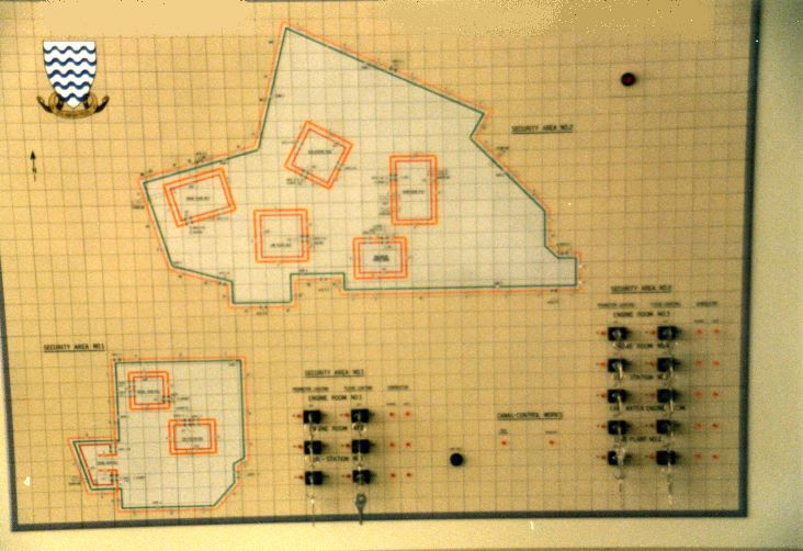
Auxiliary Systems
Time Domain Reflectometry - Can be used in systems that require breaching all elements of the system in a specific area. A pulse is sent down the cable where a specialized filter at the end absorbs the pulse, If the cable is broken and the impedance changes, a portion of the signal will be reflected back, which can then give an approximate distance to the break (or fault). This however is a separate cable system and does not run in-situ with the HV/HC systems. Link to an excellent article on TDR.
Echo-Recon using Acoustic Cable - An acoustic cable is comprised of two signal wires and a magnetic core (or leaky coax can be used). The principal follows that kinetic energy transferred to the cable by whatever means will produce an electrical signal proportional and in relation to the actual kinetic energy, ie. a pulse of varying characteristics and amplitude. This pulse travels the length of the cable in both directions (of the wire loop of dissimilar metal wires). The first signal back starts a counter and the second signal stops the counter. This provides a means of simple mathematical analysis and distance resolution.
Capacitive Signature Sensing - This method uses the reactive capacity of a link wire fence to plot intrusions. Like the acoustic cable system it does not need to be touched to generate an alarm, it simply needs to be approached. A high frequency low voltage AC signal tuned to the reactive load of the fence is sent from the end of the fence to the sensor. The sensor then plots the normal reactive points along the fence measuring areas of ground relationships, ie. fence poles. Once an standard image of the fence has been resolved during initial calibration, any changes to the interference field created by the high-q frequency fed into the fence can be intercepted analyzed and alarm points produced. Like the acoustic cable tracking and telemetry information can be produced on approach to the barrier or movement parallel to the barrier.
Ground (Vibration) Sensing - Acoustic cables can be strung along a barrier, inserted at the fence poles for telemetry or positioned as individual sensing “pods” external to the barrier system.
Acoustic Cable Telemetry and Target Differentiation - Acoustic cable and sensor systems when installed properly, will not only provide alarms based on proximity and target weight, but even direction and speed can be determined. Acoustic systems are extremely useful in analyzing and alarming for unusual situations such as tunnel building or ramming a barrier with a vehicle.
Laser Scanning / Bit Plane Imaging - Laser scanning systems used motorized paired optically adjusted laser pairs, both working in the area of 850nm to 1350nm (invisible IR). The scanning head moves in sweeps, vertical at +/- 30 degrees and horizontal at +/- 90 degrees. This allows the unit to cover a wide area. The only problem with the system is the motorized head, being fully mechanical they tend to wear out. However, 4 years ago we looked at the possibility of using a high elasticity electropolymer “muscle” which would increase MTBF over 1000%. The imaging system produces a memory based video bit plane by scanning the area constantly. Scans are updated every 2 to 3 seconds. If a change occurs in the sensors “field of view” the change can be viewed by an operator or analyzed using recognition software to generate an alarm.
Ultrasonic Scanning / Bit Plane Imaging - Ultrasonic systems work similar to the laser systems in that they “learn” their environment and alarm on changes. The difference is that we are using directed “sonar” to establish what is actually in the “field of vision.”
Thermal Imaging Cameras - Much like regular cameras except a TC camera looks more at heat signatures, information outside the normal visual range and correlates the information into readable colors. Intrusions are generally deemed to be “any unknown heat signature” or something seriously different from the background ambient conditions.
Target Analysis using AI - Regardless of which system of detection you use they all provide relational information concerning the barrier or location being protected. Some systems are more suited to brute force alarm sensing such as In-Situ measurements in the HV/HC line. Others like acoustic cable, capacitive and scanning systems produce a wealth of information that can be used for actual telemetry and monitoring of “potential” transgressions. In any border application where staffing is at a premium it is necessary to offload intelligence into the system. This is done by producing a series of AI routines that perform tasks like alarm filtering and semi-cognitive recognition of potential threats. All alarms come through and are logged and any can be accessed by an operator, but the major alarms are always brought to the forefront. As an example a person approaching the barrier, walks towards it and stops. We have a series of alarms, but there is no further motion for 30 seconds as the person tries to devise a way past the barrier. The alarm if coming from a dual sensing source of acoustic cable and capactive sensing would provide information on the actual approach (acoustic cable/sensors) and the stop point proximity to the barrier (high frequency capactive based signature sensing). Confirmation from both sources would indicate an alarm was potentially coming unless the intruder moved away, which would be sensed again by both systems. AI algorithms and routines supply the system with the ability to differentiate between common, unusual and threatening events.


 Before we get started here, let me just say that the “myth” that one cannot measure a lethal or non-lethal high voltage line and perform accurate alarm point detection “in-situ” is dead wrong, we were doing it in 1986 on fences 5km long on a side with multiple “hot” lines.